Why can two beams use nearly the same amount of steel yet show completely different resistance to bending? The answer isn't the material alone. It's where the cross-sectional area sits relative to the bending axis, and that geometric arrangement is captured by the area moment of inertia, commonly written as I.
An i beam moment of inertia calculator can produce the result quickly, but the number is useful only when you understand the geometry behind it. This guide derives the I-beam formulas, works through a custom calculation, shows how to verify results against published steel tables, and connects Ix and Iy to stress, section modulus, and deflection.
What Moment of Inertia Means for an I Beam
The area moment of inertia, also called the second moment of area, measures how a cross-section's area is distributed around a selected axis. It isn't a material property. Steel, aluminum, and timber can share the same geometric moment of inertia if their shapes and dimensions match, although their stiffness and strength will differ because their material properties differ.
The practical meaning is straightforward. A larger moment of inertia means the cross-section provides greater geometric resistance to curvature under bending. The distance from the neutral axis matters strongly because area farther from that axis contributes more than area close to it.

Strong and weak axes
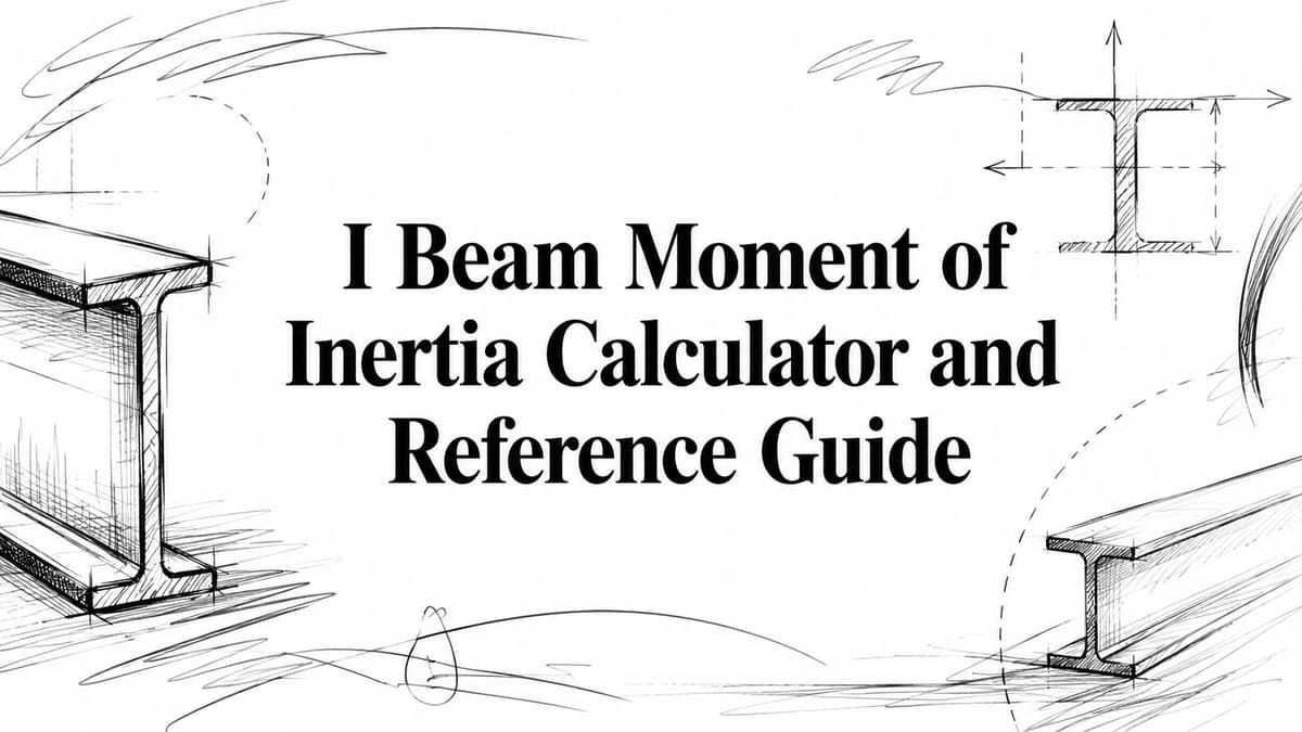
A symmetrical I-beam normally has two principal centroidal axes:
- The x-x axis, which runs horizontally through the centroid. Bending about this axis moves the flanges above and below the neutral axis. Its property is usually called Ix.
- The y-y axis, which runs vertically through the centroid. Bending about this axis moves material to the left and right. Its property is usually called Iy.
For a conventional rolled I-beam, Ix is much larger than Iy. Engineers usually place the section so loads cause strong-axis bending, because the deep overall profile puts the flanges far from the x-x neutral axis.
A flat ruler provides a useful comparison. Bend it across its broad face and it flexes readily. Turn it on edge and it becomes much harder to bend. The material hasn't changed. The orientation has changed the distribution of area around the bending axis.
Practical rule: Always state the axis with the moment of inertia. Saying “the beam has an inertia of I” is incomplete unless the reader knows whether you mean Ix or Iy.
The familiar rectangular relationship, I = bh³/12, also explains why depth is so influential. The dimension measured perpendicular to the bending axis is raised to the third power. For an I-beam, the flanges make the strongest contribution to Ix because they're separated from the neutral axis, while the web primarily connects them and contributes more directly to shear resistance than to strong-axis bending stiffness.
Deriving the I Beam Moment of Inertia Formula
Consider a doubly symmetrical I-beam with:
- b, flange width
- tf, flange thickness
- h, clear web height between the flanges
- tw, web thickness
The overall depth is D = h + 2tf. We'll derive the strong-axis moment of inertia about the horizontal centroidal axis.

Split the section into rectangles
Treat the section as three non-overlapping rectangles:
- A top flange, width b and thickness tf
- A web, width tw and height h
- A bottom flange, width b and thickness tf
Because the shape is symmetrical, the composite centroid lies at mid-depth. The centroid of each flange sits a distance
d = h/2 + tf/2
from the overall neutral axis.
For a rectangle bending about its own horizontal centroidal axis, the local moment of inertia is:
Ilocal = b tf³ / 12
for each flange, and
Iweb = tw h³ / 12
for the web.
Shift the flange inertia
The flange centroidal axes don't coincide with the overall x-x axis, so the parallel axis theorem is required:
I = Iown + Ad²
Each flange has area:
Aflange = btf
Therefore, the contribution of one flange about the composite neutral axis is:
Iflange = btf³/12 + btf d²
There are two identical flanges, so their combined contribution is:
2(btf³/12 + btf d²)
The web centroid lies on the neutral axis, so its distance term is zero. Its contribution remains:
tw h³/12
The complete strong-axis formula is therefore:
Ix = 2(btf³/12 + btf(h/2 + tf/2)²) + twh³/12
This expression is often written in an equivalent form using total depth D:
Ix = [bD³ - (b - tw)h³]/12
Both forms describe the same idealized geometry. The first form is valuable for understanding the mechanics. The second form is convenient for subtraction, because it treats the I-beam as an outer rectangle minus the two side regions removed from the web area.
Deriving the weak axis
For bending about the vertical y-y axis, the flange and web centroids all lie on that axis, so no vertical parallel-axis shift is needed for a symmetrical section. The rectangular formula is applied with the horizontal dimension cubed:
Iy = 2(tfb³/12) + htw³/12
This result is usually much smaller than Ix because the flange width is not separated vertically from the y-y axis. A calculator should report both values, and a hand calculation should label them clearly.
Worked Calculation Example with Real Dimensions
A custom example makes the geometry easier to audit than a designation alone. Consider a symmetrical built-up I-section with:
- Flange width, b = 200 mm
- Flange thickness, tf = 20 mm
- Clear web height, h = 300 mm
- Web thickness, tw = 12 mm
The overall depth is 340 mm. Keep every dimension in millimeters, and the resulting moments of inertia will be in mm⁴. If you need to move between systems, use the millimeters to inches converter before entering values into an imperial calculation.
Strong-axis calculation
The section is symmetrical, so the neutral axis is at mid-depth. The flange centroid distance is:
d = h/2 + tf/2 = 300/2 + 20/2 = 160 mm
Each flange area is:
Aflange = btf = 200 × 20 = 4,000 mm²
The local inertia of one flange about its own centroidal horizontal axis is:
Iown, flange = btf³/12
Iown, flange = 200 × 20³ / 12 = 133,333 mm⁴
The parallel-axis term for one flange is:
Ad² = 4,000 × 160² = 102,400,000 mm⁴
So one flange contributes:
133,333 + 102,400,000 = 102,533,333 mm⁴
The two flanges contribute:
2 × 102,533,333 = 205,066,666 mm⁴
The web contribution is:
Iweb = twh³/12
Iweb = 12 × 300³ / 12 = 27,000,000 mm⁴
The total strong-axis value is therefore approximately:
Ix = 205,066,666 + 27,000,000 = 232,066,666 mm⁴
Rounded appropriately, Ix is about 232.1 million mm⁴ for this idealized section.
Weak-axis calculation
For the y-y axis:
Iy = 2(tfb³/12) + htw³/12
The flange portion is:
2(20 × 200³ / 12) = 26,666,667 mm⁴
The web portion is:
300 × 12³ / 12 = 43,200 mm⁴
Thus:
Iy = 26,709,867 mm⁴
The ratio between the two values shows why orientation matters. This section is dramatically stiffer about its strong axis than its weak axis, even though the same steel appears in both calculations.
For a rolled W-shape, compare your idealized result with the manufacturer or standards-based table value for the exact designation. Differences can arise from fillets, rounded corners, tapered flanges, and dimensions that differ from nominal values. A hand calculation is an excellent verification check, but it shouldn't replace the published properties for final design.
Quick Reference Table for Common Steel I Beams
Steel tables use standardized shape designations, but the designation itself doesn't provide every geometric property. A W-shape is a wide-flange section, while an S-shape is an American standard beam section with a different flange and web geometry.
The number following the letter generally identifies the nominal depth, and the following weight designation identifies the nominal weight per unit length. Treat those labels as shape identifiers, not as substitutes for the published dimensions and section properties.
The table below is intentionally left as a reference framework rather than populated with unsupported values. No verified table data was provided for the listed designations, so inserting numerical properties would risk giving you false design information.
| Beam Designation | Depth (in) | Weight (lb/ft) | Ix (in⁴) | Iy (in⁴) |
|---|---|---|---|---|
| W8x10 | Verify in current steel table | Verify in current steel table | Verify in current steel table | Verify in current steel table |
| W8x18 | Verify in current steel table | Verify in current steel table | Verify in current steel table | Verify in current steel table |
| W10x12 | Verify in current steel table | Verify in current steel table | Verify in current steel table | Verify in current steel table |
| W10x22 | Verify in current steel table | Verify in current steel table | Verify in current steel table | Verify in current steel table |
| W12x14 | Verify in current steel table | Verify in current steel table | Verify in current steel table | Verify in current steel table |
| W12x26 | Verify in current steel table | Verify in current steel table | Verify in current steel table | Verify in current steel table |
| W16x26 | Verify in current steel table | Verify in current steel table | Verify in current steel table | Verify in current steel table |
| W16x40 | Verify in current steel table | Verify in current steel table | Verify in current steel table | Verify in current steel table |
| W18x35 | Verify in current steel table | Verify in current steel table | Verify in current steel table | Verify in current steel table |
| W18x60 | Verify in current steel table | Verify in current steel table | Verify in current steel table | Verify in current steel table |
| W24x55 | Verify in current steel table | Verify in current steel table | Verify in current steel table | Verify in current steel table |
| W24x176 | Verify in current steel table | Verify in current steel table | Verify in current steel table | Verify in current steel table |
How to use a table responsibly
Use published properties for the exact section when checking a design. If your hand result differs, inspect the assumed dimensions first, then check whether the tabulated shape includes fillets or flange taper that your three-rectangle model omitted.
For preliminary comparisons, the table columns answer different questions:
- Depth helps identify overall fit and bending geometry.
- Weight supports weight and material comparisons.
- Ix relates primarily to strong-axis bending stiffness.
- Iy matters when the beam can bend laterally or when the load acts about the weak axis.
Never substitute the strong-axis value for the weak-axis value just because both are reported in the same units.
Using the Online I Beam Moment of Inertia Calculator
A browser calculator is most useful when it exposes the same variables you'd use on paper. Enter the flange width, flange thickness, web height, and web thickness, then select a consistent unit system. For a rolled section, use the geometric dimensions that best represent the section. For a built-up beam, use the actual plate dimensions.
Entering the geometry
Start with the cross-section sketch, not the input box. Decide whether the web-height field means the clear distance between flanges or the overall depth. The formula changes depending on that definition, so read the field labels and instructions carefully.
A reliable entry sequence is:
- Choose units first. Use imperial dimensions consistently for inch-based output or metric dimensions consistently for millimeter-based output.
- Enter flange geometry. The width is measured horizontally, and the thickness is measured vertically.
- Enter the web geometry. Use the web thickness and the height specified by the calculator.
- Calculate both axes. Check the reported strong-axis and weak-axis values separately.
- Record assumptions. Save the input dimensions with the result, especially for custom sections.
The calculator applies the composite-area method internally. In effect, it evaluates the local rectangle inertias, shifts components that sit away from the neutral axis with the Ad² term, and sums the contributions.
Use the output as a check
Compare the online result with a hand calculation. If the values disagree, don't immediately assume the calculator is wrong. Common causes include entering overall depth where clear web height is expected, switching the flange dimensions, or mixing millimeters with inches.
For a broader structural check involving span, loading, bending capacity, and deflection, you can also review the beam calculator. It addresses a different part of the design problem, so moment of inertia remains a required input or underlying section property rather than a complete design decision.
A calculator should shorten arithmetic, not replace the engineer's interpretation of the section and load case.
Thecalcs provides an online I-beam moment of inertia calculator for evaluating these section properties. Use it alongside a sketch, a dimensional source, and an independent calculation when the result will affect a real structural decision.
Connecting Moment of Inertia to Section Modulus and Deflection
Moment of inertia is one link in a larger chain. Once you know I, you can calculate other section properties and use them in beam formulas, provided the assumptions behind those formulas match the actual support and loading conditions.
The elastic section modulus is:
S = I/c
Here, c is the distance from the neutral axis to the extreme fiber. For a symmetrical I-beam about its strong axis, c is commonly half the overall depth. The bending stress relationship is:
σ = M/S
where M is the bending moment and σ is the elastic bending stress.
Stiffness and deflection
For a supported beam carrying a uniformly distributed load, one familiar elastic deflection expression is:
δ = 5wL⁴ / 384EI
The symbols represent load intensity w, span L, elastic modulus E, and moment of inertia I. This equation applies to a specific support and loading arrangement. A point load, cantilever, continuous beam, or nonuniform load requires a different expression or a more complete structural analysis.
The inverse relationship between deflection and EI is the central design insight. Increasing the section's moment of inertia reduces elastic curvature when the material, load, span, and boundary conditions remain unchanged. Increasing E can also increase stiffness, but changing the cross-sectional geometry may be more practical than changing materials.

Radius of gyration
The radius of gyration connects inertia to area:
r = √(I/A)
It's especially important in column work, where slenderness and buckling depend on the least radius of gyration. A beam with a strong Ix can still have a relatively small Iy and therefore a smaller weak-axis radius of gyration.
This is why a bending check shouldn't stop after finding Ix. Review Sx, Sy, rx, and ry when the member can experience bending in more than one direction. For roof or frame systems, the supporting arrangement may also require checks beyond a single beam equation. A separate truss calculator can help with truss-specific geometry and load paths, but it doesn't eliminate the need to identify the relevant section properties.
Common Calculation Mistakes and How to Avoid Them
Most wrong I-beam results come from a small set of repeatable errors. The arithmetic often looks clean, which makes geometry and unit checks more important than extra decimal places.

The parallel-axis error
A frequent shortcut calculates each flange's local inertia and adds the two values to the web. That misses the dominant effect of moving the flange areas away from the neutral axis.
The correct flange contribution is:
Iflange = Iown + Ad²
The distance d must be measured from the flange centroid to the composite neutral axis. Because the distance is squared, a small dimensional or transcription error can materially change the result.
The geometry and unit errors
Watch for these specific traps:
- Using total depth as web height. If the web-height variable means clear height, enter the distance between flange boundaries, not the full section depth.
- Mixing unit systems. Dimensions must use one unit throughout. Since inertia has length raised to the fourth power, converting the final number after mixing inputs won't repair the calculation.
- Treating the I-beam as a solid rectangle. A solid rectangle with the same outside dimensions contains material where the I-beam has open space. It will overstate the actual area and inertia.
- Confusing Ix and Iy. The strong-axis result belongs to the horizontal centroidal axis for the usual upright I-section. Confirm the axis shown in your sketch.
- Using material properties in a geometric calculation. Elastic modulus affects beam stiffness through EI, but it doesn't belong inside the area moment of inertia formula for a homogeneous section.
A short audit routine
Draw the section, label both axes, calculate the centroid, and list every rectangle once. Then write units beside every input and check that the output has units of length to the fourth power.
Audit habit: If a result looks unexpectedly large, inspect the cubed dimensions and the flange offset before recalculating every line.
For a non-symmetrical or built-up section, don't assume the neutral axis is at mid-depth. Find the composite centroid first, then apply the parallel axis theorem to every component.
Frequently Asked Questions About I Beam Moment of Inertia
Does beam length change the moment of inertia?
No. The area moment of inertia belongs to the cross-section, so it doesn't change merely because the member is longer. Length enters beam response through equations for deflection, stability, and internal forces.
How do I handle a tapered beam?
A tapered member doesn't have one constant cross-section. Divide its length into regions, calculate the local properties, and use an appropriate variable-section beam method. A simplified average section may support early estimates, but it isn't a substitute for analysis when taper materially affects stiffness.
Is area moment of inertia the same as mass moment of inertia?
No. The area moment of inertia describes how area is distributed in a cross-section and is used in bending and deflection formulas. Mass moment of inertia describes how mass is distributed about a rotational axis and is used in dynamics.
Can I use the formula for aluminum or timber?
Yes, for a homogeneous I-shaped cross-section, the geometric Ix and Iy calculation is unchanged. Material enters later through elastic modulus, allowable stress, connection behavior, and design code requirements.
What about a plate girder with cover plates?
Model each plate and web as a component. Find the composite centroid, calculate each local inertia, shift each component with Ad², and sum the results. If materials differ, use transformed-section methods rather than treating the entire assembly as one homogeneous shape.
Does a calculator complete a structural design?
No. It gives a section property, not a full design approval. You still need to check loads, supports, lateral stability, shear, connections, serviceability, material behavior, construction tolerances, and the governing code.
Use thecalcs to calculate and verify I-beam section properties, then carry the result into beam strength and deflection checks with clearly documented assumptions. Visit thecalcs to work through the calculator and compare your result with a hand-derived value before using it in a project.