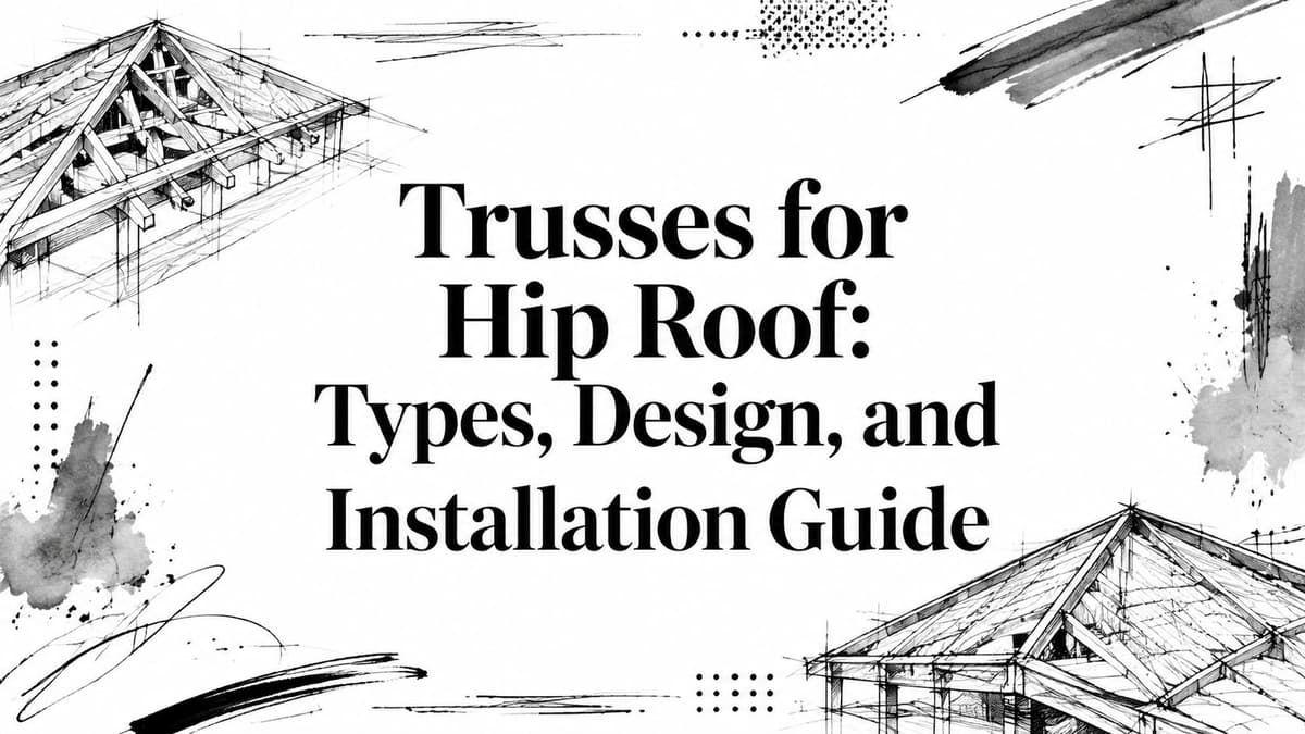
You're looking at a house plan with four sloping roof faces, a few awkward corners, and a framing estimate that seems higher than a simple gable roof. The natural question is whether trusses for a hip roof are worth the added complexity, or whether traditional rafters would be easier and cheaper.
The answer depends less on appearance than on the load path. A hip roof truss package uses a coordinated group of engineered members, including a truncated girder, hip trusses, and jack or creeper trusses. Those parts have to work together, and the cost, wind performance, span, and installation requirements all follow from that arrangement.
The Structural Logic of Hip Roof Trusses
A homeowner may choose a hip roof because it gives the house a compact, finished appearance. A contractor sees a different problem. Four sloping roof planes meet at corners and perimeter transitions, so the framing must collect those loads and deliver them to the walls without relying on improvised site cuts.
That's where the hip truss system earns its place. It's a modern engineered roof-framing method that developed alongside the wider adoption of prefabricated timber trusses in North American housing. One industry guide reports that wood trusses are used in more than 75% of homes built in the United States and Canada today (Alpine roof truss guide). The significance isn't just manufacturing volume. Factory-built components let designers apply repeatable rules to roof shapes that would otherwise require extensive on-site layout and cutting.

A roof shape that solves a framing problem
In a simple gable roof, many common trusses can span between the side walls while the end walls close the roof shape. A hip roof removes those vertical gable ends and replaces them with sloping sections. The framing system must therefore support the shortened roof planes at the ends and guide their reactions into the building's wall lines.
The key member is the truncated girder, sometimes called the girder station in layout discussions. It carries the concentrated loads from the hip portions and transfers them toward the side walls. Half trusses and jack trusses then create the stepped, sloping geometry between the girder, hip lines, and ridge.
That arrangement makes the hip roof more than an aesthetic selection. It's a load-path solution that lets builders use engineered, repeatable components while still handling complex corners. Traditional site-cut framing can work, but it demands accurate field layout, experienced carpentry, and careful coordination between rafters, hips, valleys, and bearing points.
For a useful overview of the fundamentals before reviewing a truss package, compare the framing terminology in these Seattle roof frame basics.
Practical rule: Treat the hip roof as a coordinated structural system. Choosing the roof outline first and asking how to support it later is how bearing and connection problems enter a project.
Core Components and Load Transfer
The most important question in a hip roof is not “How many trusses do I need?” It's “Where does each reaction go?” A complete package normally combines several truss forms so the roof can move from broad, regularly spaced framing into the concentrated geometry at each corner.

The truncated girder carries the concentration
The truncated girder is the primary transfer member. Instead of allowing every hip-area reaction to land independently on a small section of wall, the girder gathers those forces and directs them into its designated bearings at the side walls.
Its position matters. The girder station determines where the transfer occurs, while its bearing and end connections determine whether the supporting wall line can receive the reaction safely. If the girder is shifted in the field, supported on an unplanned partition, or installed without the specified bearing, the truss system no longer matches the design assumptions.
The girder also has to be considered alongside the roof diaphragm and the wall framing. Gravity loads are only part of the picture. Wind can create uplift and lateral forces that travel through roof sheathing, truss restraints, wall connections, and down into the structure below.
Hip, jack, and creeper trusses complete the geometry
Hip trusses bear at the building corners on one end and at the truncated girder on the other. Their job is to establish the diagonal hip geometry and provide a structural transition between the roof perimeter and the main roof framing.
Jack and creeper trusses fill the spaces between the hip line and the ridge or between the girder and adjacent framing. They're shorter than the main trusses, but their smaller size doesn't make them unimportant. Each one still needs the correct orientation, spacing, bearing, and restraint.
A practical review should verify:
- Girder location: Confirm the station matches the truss layout and architectural plan.
- Bearing: Check that every designed support lands on framing capable of carrying the reaction.
- Connections: Review uplift and lateral connection details rather than relying on roof shape alone.
- Bracing: Follow the manufacturer's permanent and temporary bracing instructions.
- Continuity: Make sure sheathing, blocking, and wall framing preserve the intended load path.
When a girder reaction needs a quick preliminary check, a beam calculator for home-service projects can help organize inputs. It doesn't replace engineered truss drawings or a code review, but it can clarify why a concentrated reaction deserves more attention than an ordinary truss bearing.
Span Limits and Pitch Considerations
A hip roof can fit the footprint and still exceed practical truss limits once span, pitch, and loading are combined. The manufacturer configures the package around the actual bearing-to-bearing span, roof slope, overhangs, and the transition into the hip framing. Changing any of these can alter member geometry and web forces.
A residential manufacturing manual shows hip-end options for roof spans of approximately 6 to 13 meters, with pitches from 15° to 45° (Alpine roof truss guide). Treat those figures as screening values, not a universal design range. Snow, wind, materials, openings, bearing conditions, and the selected truss family determine whether a proposed layout works.
Typical Hip Truss Design Parameters
| Parameter | Typical Range |
|---|---|
| Hip-end roof span options | About 6 to 13 meters |
| Roof pitch range shown in a residential manual | 15° to 45° |
Work through the design in this order:
- Measure the structural span. Use the bearing-to-bearing dimension, not the roof covering length or eave-to-eave measurement.
- Confirm the pitch. Slope changes the truss profile and hip transition. Do not plan to alter a standard truss on site to achieve a different roof angle.
- Provide loading information. Snow, wind, roof covering, ceiling materials, and permanent equipment belong in the information sent to the manufacturer or engineer.
- Locate the girder station. The truncated girder must align with its designed supports and with the hip and jack trusses shown on the layout. Moving it changes concentrated reactions and can invalidate the load path.
- Review code requirements and engineered drawings. Hipped-roof provisions show allowable spans falling as design wind speed rises. One code table lists maximum roof spans from 45 feet at 120 mph ultimate design wind speed down to 24 feet at 195 mph for a 12-foot building span (hipped-roof code guidance).
Pitch also affects material quantities and installation handling. A steeper roof can increase truss height and lifting difficulty, while a shallow pitch may require closer attention to drainage, overhang details, and member forces. Confirm these effects before fabrication rather than relying on field changes.
A rafter calculator for home-service planning can organize preliminary slope and length inputs. It does not replace engineered hip-truss drawings, bearing checks, or code review.
Cost Drivers and the Hip Premium
A hip roof can exceed a comparable gable roof budget before any framing begins. The added cost comes from engineered transitions, the concentrated truncated girder, more detailed drawings, lifting logistics, and the labor needed to place shorter components accurately around the perimeter.
One 2026 cost guide reports hip truss packages at approximately $6,000 to $16,000 for a mid-size home, with engineering or blueprint stamping ranging from $350 to $1,800 and installed costs often around $6.50 to $11.50 per square foot (hip roof truss price guide). The same source also lists standard-home roof truss costs at $7,500 to $35,000, while hip trusses are commonly quoted at $100 to $400 per unit. Those figures describe different scopes. The package range includes a broader project allowance, while the per-unit figure covers individual hip trusses and does not by itself include stamping, delivery, crane work, or installation.

Where the extra money goes
Engineering and stamping become larger line items when the roof has unusual spans, irregular geometry, high wind demands, or jurisdiction-specific submission requirements. The girder, hip trusses, and jack trusses must work as one load path, so revisions to one component can require updated calculations and drawings for the surrounding members.
Crane or lift requirements depend on site access, component size, crew method, and safe staging space. A tight urban lot or steep site can make mechanical placement practical even when individual wood members appear manageable on paper.
Labor varies by region and crew familiarity. A gable package gives framers repeated components and a straightforward setting sequence. A hip package requires more identification, alignment, blocking, and perimeter work, especially where the truncated girder concentrates reactions at its supports.
| Cost driver | Why it changes the budget |
|---|---|
| Engineering and stamping | Complex geometry and code documentation can require additional design work. |
| Crane or lift access | Limited staging or difficult roof placement can add equipment and scheduling costs. |
| Labor | Hip transitions require more layout and coordination than repetitive gable framing. |
| Roof complexity | Multiple ridges, offsets, overhangs, and irregular corners increase detailing. |
Compare the complete installed scope, not only the hip-versus-gable truss price. Include design, delivery, lifting, bracing, sheathing coordination, and inspection requirements. A lower truss quote can still produce a higher project total if it excludes the engineering stamp or the equipment needed to set the girder and hip components.
A short video can illustrate the physical setting process and the equipment decisions that affect the estimate.
Wind Resistance and Structural Performance
A hip roof can start with a favorable wind shape because all four sides slope down from the ridge. That reduces the broad vertical end-wall exposure found in a conventional gable arrangement, but geometry alone does not make a roof storm-proof.
Storm damage shows how the load path can break. Houses with partial roof-framing failures and roof-to-wall connection failures have been documented in damaged areas. The practical lesson is direct: wind performance depends on bracing, sheathing continuity, and connections, not only on the roof outline. Code provisions for hipped roofs also require the design to account for how those components work together (study and hipped-roof guidance).
The roof covering isn't the wind system
Wind uplift starts at the roof surface, then travels through the covering and sheathing into the trusses. Restraints and roof-to-wall connections carry those forces into the walls and foundation.
A local weakness can interrupt that route. Missing restraint, an incorrectly installed connector, a break in the sheathing line, or inadequate bearing can keep the roof from sharing loads as designed. The truncated girder requires particular attention because the hip framing delivers concentrated forces to it, and it must transfer those reactions into the supporting side walls.
The structural package should identify:
- Permanent bracing: Members that prevent truss instability after temporary erection supports are removed.
- Lateral restraint: Details that limit movement of individual truss members.
- Roof-to-wall connections: Hardware and fastening schedules selected for the applicable uplift forces.
- Diaphragm continuity: Sheathing layout and fastening that distribute lateral forces across the roof plane.
- Wall and foundation transfer: A continuous route from roof connections through the supporting structure.
A hip roof improves the starting geometry. It does not correct weak connections or missing bracing.
Owners comparing roof upgrades with structural work should keep those as separate decisions. A resource on metal roof financing options can help organize the roofing budget, but financing does not change the load requirements shown in the truss drawings. The engineer still needs to verify uplift forces, connection details, bearing conditions, and the complete load path before construction.
Installation Overview and Engineering Requirements
Hip trusses need more than a lifting plan and a stack of labeled pieces. The crew has to protect the designed sequence, keep bearings aligned, and install temporary and permanent bracing before the roof system is exposed to construction loads or weather.

Start with the supports
Before delivery, verify the wall dimensions, top plates, bearing locations, anchor details, and access for staging or mechanical lifting. The girder bearing deserves a separate check because it carries a concentrated reaction rather than the more distributed reaction associated with an ordinary truss.
The setting sequence usually follows the engineered layout. Main trusses, truncated girder components, hip trusses, and jack or creeper trusses must be identified and placed where the drawings show them. Substituting one piece for another because it “looks close” is not a safe field adjustment.
Align, brace, and review
Once the trusses are set, the crew aligns and plumbs them before installing the roof sheathing. Temporary bracing holds the system during erection, while permanent bracing and restraint prevent later movement under gravity and wind loads.
A reliable field checklist includes:
- Site preparation: Confirm access, wall readiness, delivery staging, and the drawing set.
- Truss setting: Place components in the specified order and protect them from damage during lifting.
- Alignment: Check spacing, plumb, bearing, ridge alignment, and girder position.
- Bracing: Install temporary and permanent restraint exactly as detailed.
- Engineering review: Resolve field deviations before covering the framing.
Use a roof truss calculator to organize preliminary quantities and project inputs, then rely on the sealed design documents and manufacturer instructions for construction decisions.
The final review should occur before sheathing hides the framing. Confirm that the girder bears correctly, connections match the schedule, bracing is complete, and no field-cut member or altered connector has changed the approved load path.
Common Misconceptions About Hip Roof Trusses
The most persistent misconception is that a hip roof is automatically the best storm solution. Its sloping end geometry can reduce direct wind exposure compared with a gable end, but the roof still needs a continuous load path, adequate diaphragm action, proper restraint, and correctly installed roof-to-wall connections.
A simpler gable roof can sometimes be the better project choice if its bracing and connections are easier to detail, inspect, and install correctly. Complexity only creates value when the design team and framing crew can execute it accurately.
Other assumptions cause trouble:
- “The girder can sit wherever the framing allows.” Its station is part of the engineered layout.
- “Jack trusses are minor pieces.” They complete the hip transition and still require correct bearing and restraint.
- “A crane automatically means the design is oversized.” Lifting needs depend on access, staging, component handling, and crew method.
- “A standard truss can be trimmed in the field.” Any change can affect the approved structural behavior and should be reviewed by the designer.
Choose the hip system because it suits the building's geometry, hazard exposure, and budget, not because the roof shape carries a universal performance guarantee.
For preliminary span, pitch, beam, rafter, and installation-cost planning, thecalcs provides browser-based home-service calculators that help organize project inputs before you request final engineering. Visit thecalcs to compare the relevant roof-framing calculations and turn an initial hip-roof concept into a clearer discussion with your contractor or structural designer.